
Technical coordination guide
3D Aluminum Ceiling Design Coordination and Panel Segmentation
A practical pre-fabrication workflow for architects, ceiling contractors, MEP coordinators and project buyers working with modular geometric aluminum ceilings.
Quick answer: Coordinate the ceiling as a numbered system, not as isolated shapes. Freeze the design surface, divide it into buildable panel families, resolve joints and perimeter closures, then coordinate lighting, MEP openings, access, suspension and installation zones before shop drawings are approved.
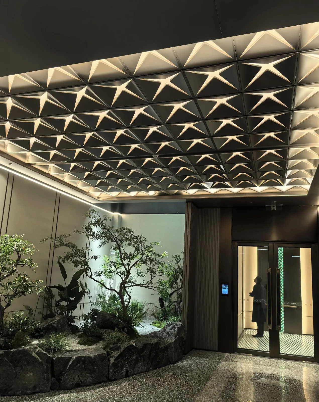
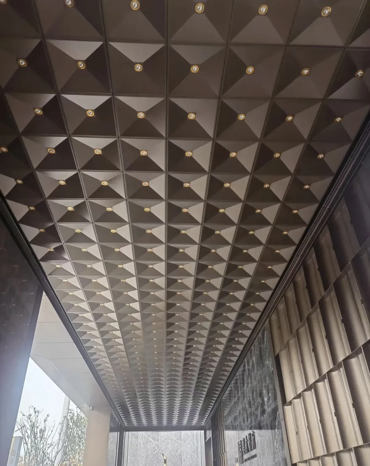
Image context: The photographs are shown only as an architectural application reference. They do not identify the pictured installation as a Punchuk-supplied, manufactured or installed project.
This guide addresses design-to-production coordination. For system forms, finishes and typical interior uses, see the 3D faceted aluminum ceiling panels page. Where the surface is continuously curved in two directions, use the separate double-curved ceiling workflow; its forming and panelization logic is different.
1. Freeze the design inputs before segmentation
A concept rendering is useful for intent, but a coordinated ceiling needs measurable and revision-controlled information. The design team should establish:
- reflected ceiling plan, setting-out grid, datum levels and perimeter interfaces
- 3D surface or clearly dimensioned sections showing high points, low points, folds and transitions
- lighting, sprinklers, grilles, detectors, speakers, cameras and maintenance-access zones
- structural soffit, hanger zones, carrier direction, support spacing and prohibited fixing areas
- finish reference, visible direction, gloss target and sample-approval requirement
- model version, drawing revision and the person responsible for geometry sign-off
2. Convert the design surface into module families
Panel segmentation should reduce one-off parts without flattening the intended geometry. Start from the architectural grid and identify repeatable footprints, fold patterns and depths. Assign a family code to each repeatable module; reserve unique codes for perimeter pieces, transitions, service panels and access units.
Reference geometry
Fix control points, fold lines, facet angles and module depth from the approved model or sections.
Family logic
Group panels that share footprint, fold pattern, returns and fixing details. Do not group visually similar panels if their interfaces differ.
Orientation rule
Add a consistent arrow or local axis so mirrored or rotated modules cannot be installed in the wrong direction.
3. Panel segmentation workflow
- Set the primary grid. Use architectural datums and visible focal lines before choosing panel edges.
- Place major joints. Align joints with bays, lighting bands, transitions and access strategy where practical.
- Control panel size. Check forming, handling, coating, packing, lifting and access constraints—not drawing size alone.
- Resolve perimeter closures. Avoid leaving narrow or irregular closure pieces to site improvisation.
- Assign module numbers. Use zone, row and panel-family codes that continue from shop drawing to packing list and installation plan.
- Review the complete ceiling. Check joint continuity, visual rhythm, service collisions and the removal path for access modules.
4. Coordinate joints, tolerances and interfaces
The visual result depends on consistent joint width, but the drawing must also allow for production, coating, support and site tolerances. Record the design joint separately from the permitted tolerance and accumulated grid adjustment.
| Coordination point | Drawing decision | Release check |
|---|---|---|
| Module joints | Nominal width, open or closed appearance, backing color and alignment rule | Joint rhythm remains continuous across family changes |
| Perimeters | Shadow gap, trim, closure panel, movement allowance and site-measurement responsibility | No unresolved narrow cuts or blocked removal paths |
| Transitions | Flat-to-faceted, faceted-to-curved, wall, column and bulkhead details | Adjacent trades share the same datum and interface dimension |
| Tolerances | Panel, carrier, support and site tolerances plus where adjustment is absorbed | Accumulated tolerance does not shift the focal grid |
5. Coordinate lighting, MEP openings and access
Locate openings before fabrication and check them against fold lines, returns, stiffeners, brackets and carriers. Downlights need center coordinates and cut-out sizes; linear lights need channels, end details, cable access and heat clearances. Sprinklers, diffusers and sensors may require independent support. Mark removable modules and show the direction in which each unit disengages.
6. Coordinate suspension and support
The visible panel layout and support concept must be checked together. Define carrier direction, hanger spacing, edge restraint, bracket locations, allowable adjustment and access above the ceiling. Final support sizing and loading remain subject to the approved project specification and engineering review.
General material starting points: 2.0, 2.5 and 3.0 mm
Thickness is a coordination input, not a universal product promise. For solid aluminum interior modules, the following values are common comparison starting points; final selection depends on geometry, panel size, returns, support spacing, openings, handling and project performance requirements. See the broader aluminum panel thickness guide.
| Nominal thickness | General starting point | Items to verify |
|---|---|---|
| 2.0 mm | Smaller, shallow modules with close support and limited openings | Handling rigidity, flat areas, returns and local deformation |
| 2.5 mm | A frequent middle option for many formed modular ceilings | Module depth, service cut-outs, reinforcement and suspension |
| 3.0 mm | Larger, deeper or more demanding modules where additional rigidity may help | Weight, forming sequence, support capacity and installation handling |
7. Use a prototype or coordinated mock-up
A prototype can verify the fold, joint, finish, lighting interface and removal method before quantity production. For visually sensitive ceilings, approve a representative multi-module area rather than a single isolated panel so joint rhythm and accumulated tolerances can be reviewed.
Deliverables by design stage
| Stage | Recommended deliverable | Decision gate |
|---|---|---|
| Concept | Reference geometry, visual priorities and indicative module grid | Confirm the ceiling is faceted rather than continuously double-curved |
| Design development | Coordinated RCP, sections, services overlay and preliminary support zones | Freeze major joints, perimeter logic and access strategy |
| Shop drawing | Numbered panel plan, family details, folds, returns, openings, brackets and finish schedule | Architect, contractor and relevant trades approve one revision |
| Production release | Approved drawings, model, panel schedule, sample record and packing-zone plan | No unresolved geometry, finish or interface hold points |
RFQ checklist for a coordinated review
Send enough information to distinguish confirmed requirements from open design decisions:
- reflected ceiling plan, sections and available 3D or BIM model
- module grid, approximate panel dimensions, folds, depth and joint intent
- lighting and MEP layouts, cut-out sizes and maintenance-access requirements
- support concept, soffit constraints, installation sequence and site tolerances
- preferred alloy and initial 2.0, 2.5 or 3.0 mm comparison point
- finish system, color reference, gloss and sample requirement
- quantity or area by zone, project country, packing limits and delivery schedule
How Punchuk supports the design-to-production handoff
Punchuk can review project drawings, develop panel families and fabrication details, coordinate CNC cutting, folding or forming, specified reinforcement and coating, then perform dimensional and visual QC, module labeling, protective export packing and delivery coordination. The final geometry, material, support and performance requirements follow the approved project documents. Review the factory capability page for the wider manufacturing scope.
Frequently asked questions
What is panel segmentation for a 3D aluminum ceiling?
It is the process of dividing the approved ceiling geometry into buildable, numbered panels and repeatable module families while coordinating joints, perimeters, openings, supports, packing and installation sequence.
Should panel joints follow the architectural grid or the 3D form?
Both must be reviewed together. Primary joints normally respect the architectural setting-out grid and visual focal lines, while secondary segmentation responds to forming, handling, access, coating and support limits.
When should lighting and MEP openings be fixed?
They should be coordinated before shop drawings are approved and before cutting begins. Late openings may conflict with folds, returns, reinforcement, brackets or carriers.
Is 2.0, 2.5 or 3.0 mm aluminum always required?
No single thickness suits every module. These are general comparison starting points; geometry, size, support spacing, openings, loads, handling and the approved specification determine the final selection.
What should be approved before production release?
Approve the model or sections, numbered panel plan, module-family details, joints, perimeters, lighting and MEP openings, support interfaces, removable modules, finish sample, tolerances and drawing revision.
Send a ceiling model or drawing for coordination review
Share the latest RCP, sections or model, service overlay, finish target, approximate quantity and project location. Punchuk can identify the information still needed for panelization and fabrication review.
Related exterior folded-module case
For a different application intent, review the folded aluminum feature column and canopy case study. It documents an exterior elevator feature from workshop fit-up to site installation rather than a modular interior ceiling.
 Indonesian
  English
  Vietnamese
  Malay
Malay  Arabic
  Thai
Thai  Chinese
  Russian
  Kazakh
  Spanish