
Solid aluminum facade accuracy is not controlled by one factory check or one site inspection. It depends on matching released drawings and panel references to clear setting-out datums, reviewing the first installed conditions, protecting finished surfaces and holding final closures until the required records are complete.
This guide is for facade consultants, contractors, importers and project buyers. It focuses on the handoff between fabrication release and site work. Project drawings, engineering requirements, approved samples and the project inspection plan remain the controlling references. The review points below help the responsible parties coordinate fabrication and installation accuracy without replacing those documents.
The eight photographs on this page show solid aluminum panels manufactured and supplied by PUNCHUK. They are visual references for coordination discussions. They do not show PUNCHUK installing, measuring, supervising or inspecting the work. They also do not establish project names, locations, panel thicknesses, alloys, coatings or performance values.
A018, A068 and A093 are three views of the same project. A076, A049 and A035 come from three separate projects. A057 and A099 are standalone references.
Start with the released information
A finished elevation can look simple even when the fabrication information behind it is not. Before panel production is released, the consultant and contractor should identify the drawings that govern the work and confirm that the panel schedule refers to the same revision.
The information should locate panel joints, inside and outside corners, window and door returns, soffit interfaces and areas that will require closure panels. Panel references and installation orientation also need to be clear. Where dimensions depend on site measurement, the drawings should identify the relevant datum rather than leaving the factory to interpret photographs or isolated measurements.
Buyers who are still choosing the panel type can review PUNCHUK’s solid aluminum panel options before confirming the fabrication scope.
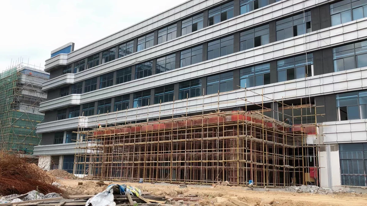
A wide construction view provides useful context. It shows how cladding bands relate to glazing zones and floor lines, but it cannot confirm the dimensions or alignment of an individual panel. Building-scale coordination and panel-level checks need separate records.
Use control lines to review panel joints
Panel joints form part of the architectural geometry. A small local adjustment may affect the next panel, the next opening or a joint line that continues around a corner.
The site team should compare the first installed panels with the approved layout and setting-out references before the same condition is repeated across a larger area. Horizontal and vertical joints should follow the specified datums. Changes in direction deserve particular attention because two acceptable surfaces can still meet awkwardly at a corner.
The project documents must define joint width, movement allowance, sealant treatment and any drainage requirements. A photograph can help identify where these questions occur, but it cannot provide the acceptance values.
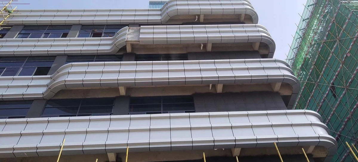
The hero image gives a close view of curved edges and several joint transitions. It is useful for discussing how visible lines meet at projecting forms. It is not a dimensional inspection record.
Resolve returns and adjacent interfaces before production
Window and door returns often bring several trades into a narrow space. The face panel, folded edge, opening frame and adjacent finish may all need to finish against one coordinated line.
For each opening, the drawing should state the return depth, corner geometry and relationship to the frame. It should also show where the visible joints terminate and whether a narrow closure piece is required. If another trade controls the final datum, that responsibility should be settled before the affected panels are released.
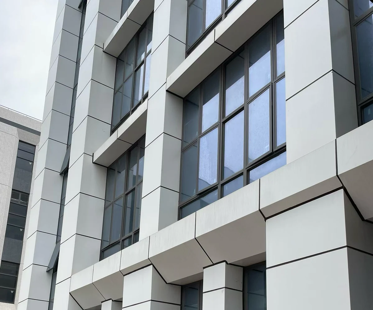
The photograph shows solid aluminum panel returns around tall openings and columns. The visible geometry is clear, but concealed fixings and other system details are outside the evidence shown.
This is one reason a buyer should not compare quotations by area alone. Returns, folded edges, corners and shaped components need to be identifiable in the drawings and panel schedule so that suppliers are pricing the same manufacturing scope.
Protect the finished surfaces
Protection needs to cover more than transport. Panels may be exposed during unloading, storage, lifting and later work by nearby trades.
The project handling method should explain how each package is identified, how panels are separated and stored, and how finished faces and formed edges are protected during lifting. Site teams also need a simple process for recording visible damage before a panel is installed.
Temporary film should be handled according to the applicable product instructions and site conditions. Removing it too early may expose the surface to other work. Leaving it in place without checking the relevant instructions may create a different problem. The responsible parties should agree on the timing rather than relying on a generic rule.
Set a hold point before closure
The last panel in an area can hide work that will be difficult to reach again. The project inspection plan should therefore state what must be reviewed before a closure panel is fitted and who may authorize that step.
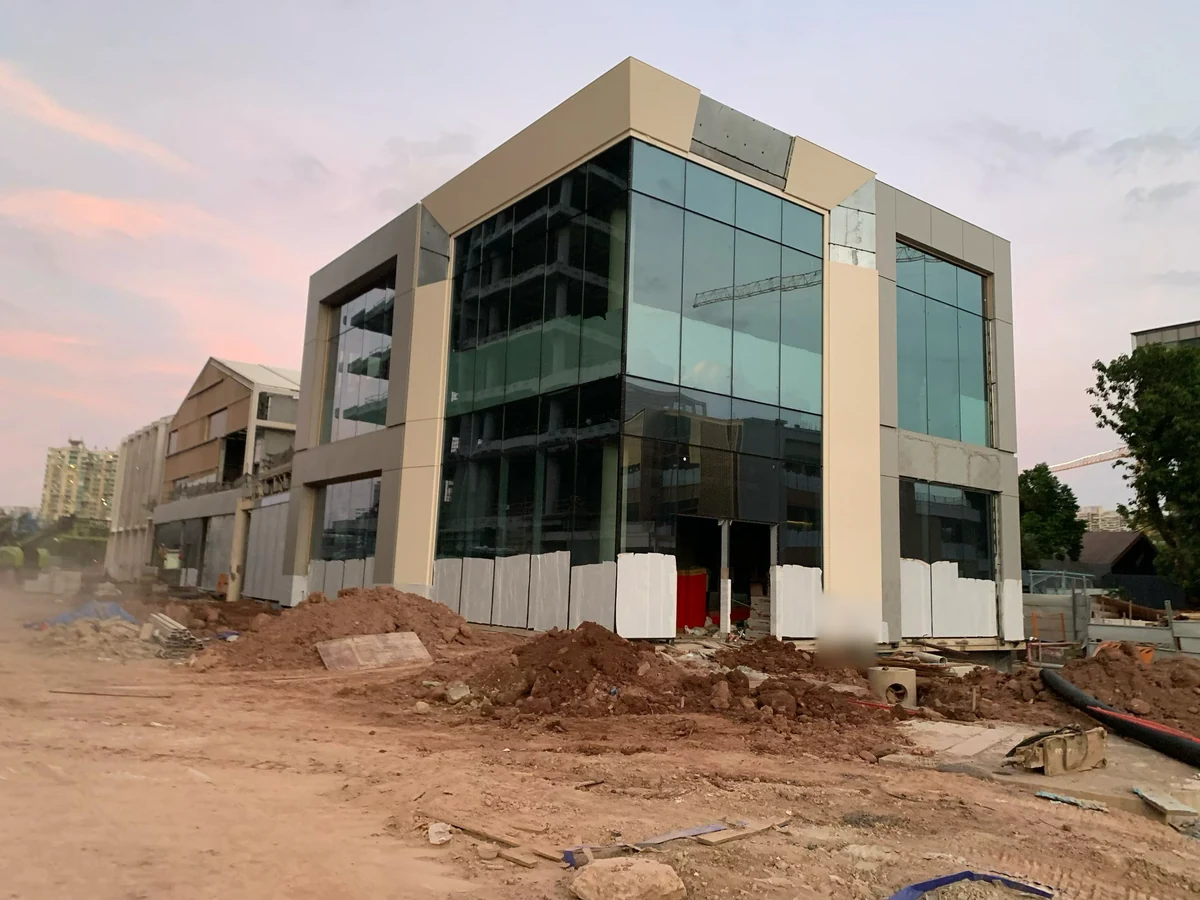
The photograph shows panels beside glazing and areas that are still open. This is the stage at which the responsible site team may need to review the support, concealed components and adjoining construction required by the approved facade design. Any required photographs, inspection records or corrective work should be completed before access is lost.
The exact checks depend on the system and assigned responsibilities. They may include the supporting structure, brackets, fasteners, membranes, drainage provisions or service access, but only where those items are part of the approved project documents.
Treat site measurements as controlled information
A useful site measurement needs context. The record should identify the location, datum, direction, date, drawing reference and responsible party. A number written on an unreferenced photograph is difficult for another person to verify.
Where actual construction differs from the released information, the affected panels should not be changed informally. The difference should be recorded and resolved through the project’s drawing and approval process. This reduces the chance that the factory, consultant and site team act on different revisions.
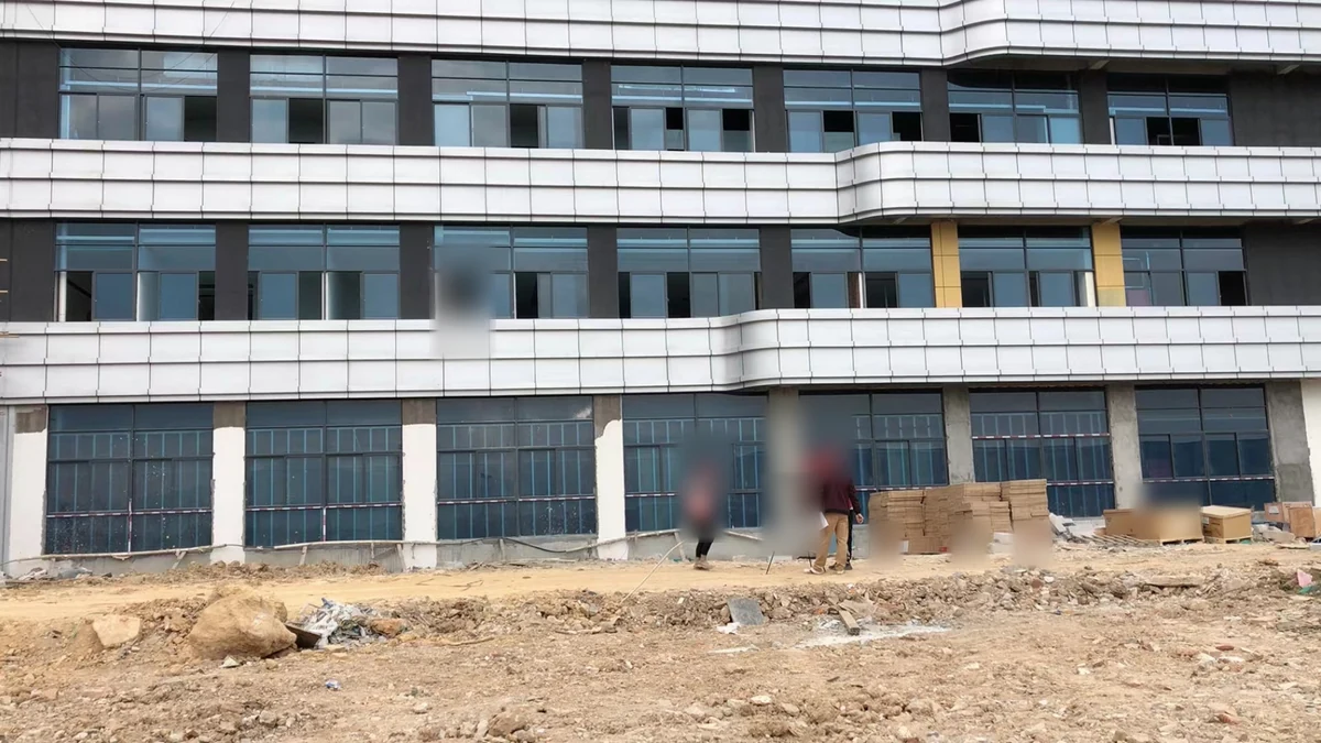
The photograph shows measurement activity beside the facade. It does not identify who carried out the measurement, what was measured or whether the result was accepted.
Review curved work from several viewpoints
A close view of a curved facade can reveal local joints and returns. A wider view shows whether bands and openings read continuously across the elevation. Both are useful, but neither replaces the agreed measurement and acceptance method.
The following three photographs show the same project from different positions.
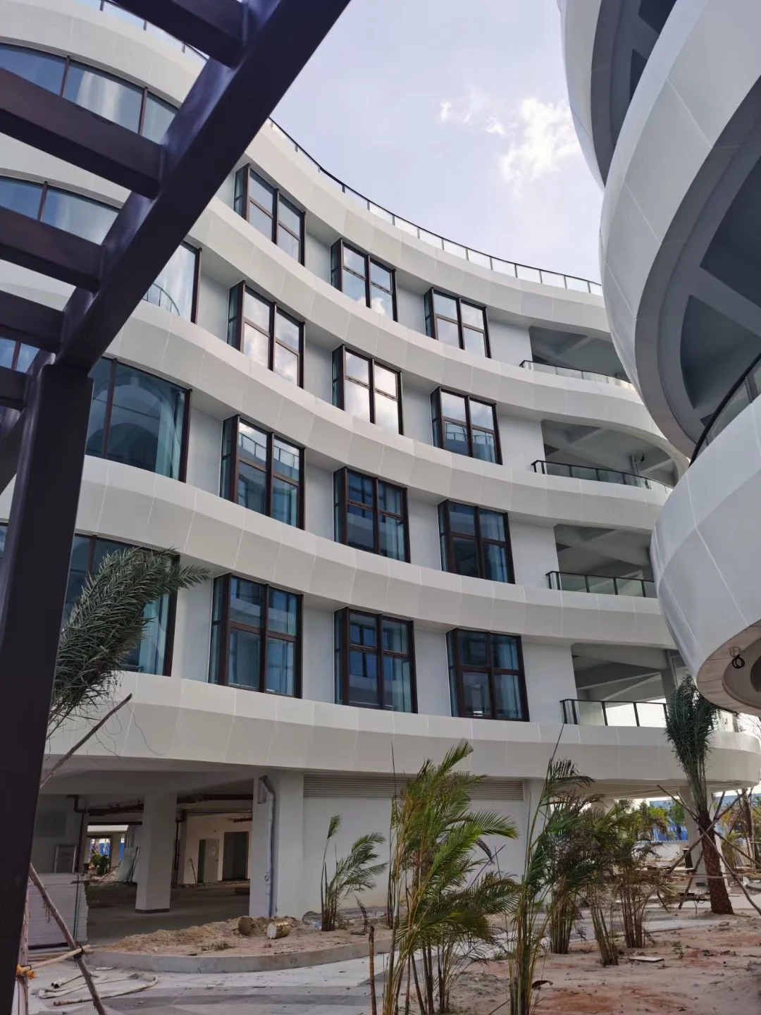
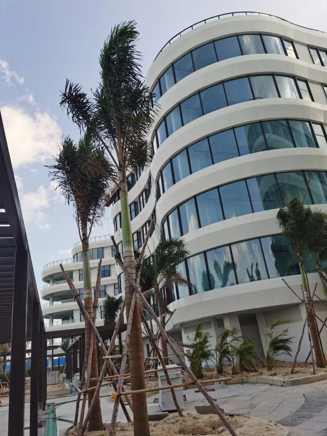
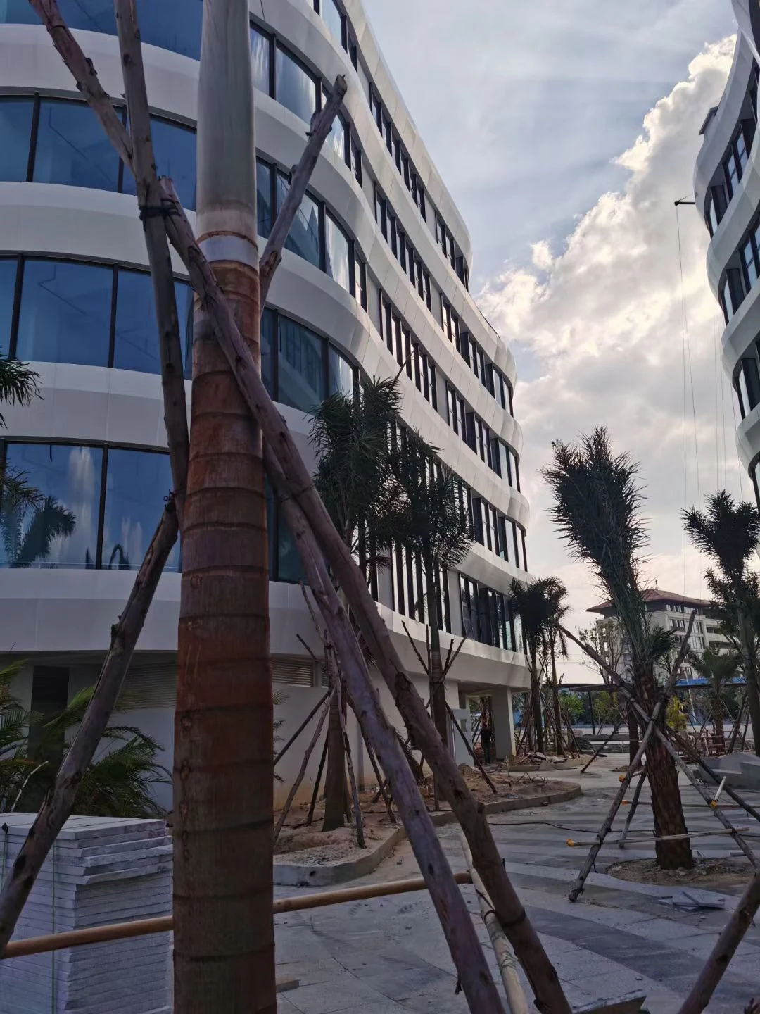
Viewing angle, daylight and nearby landscaping can change how curved surfaces and joints appear in a photograph. The project team should compare the work with the approved geometry, panel layout and accepted sample or mock-up where one forms part of the project requirements. Projects that need geometry guidance can also review the separate guide to single and double curved solid aluminum panels.
Accuracy and coordination checks by project stage
The solid aluminum panel specification guide explains the product information that should accompany the drawings. The table below focuses on how the released information should be checked as work moves toward the site.
| Stage | Coordination points |
|---|---|
| Before fabrication release | Current drawing revision, panel schedule, site-dependent dimensions, joint lines, returns, corners, finish reference, panel identification and approval responsibilities |
| Before delivery | Package identification, handling instructions, storage area, installation sequence, site access and readiness of adjoining work |
| First installed area | Setting-out references, panel orientation, joint continuity, opening interfaces and any repeatable condition that would be costly to adjust later |
| Before closure | Required concealed-work review, unresolved deviations, project records, access requirements and authorization under the project inspection plan |
| Before handover | Joint and interface review, removal of temporary protection, damage record, punch list and relevant handover documents |
Project-specific dimensions, tolerances and acceptance values should come from the approved project documents. They should not be copied from an unrelated project or inferred from the photographs on this page.
Common buyer questions
How is fabrication and installation accuracy controlled for curved or shaped panels?
The responsible parties need one approved geometry, traceable panel references, clear site datums and a controlled process for recording changes. The first repeated condition should be reviewed before it is reproduced across a larger area. Curved or shaped work also needs enough views and sections to connect the released geometry with the actual setting-out points.
When should panel alignment be reviewed?
Review the intended alignment during drawing coordination. Check it again against the setting-out references when the first panels are installed and before the same condition is repeated across the elevation. The project inspection plan should define any formal hold points.
What should a site measurement record contain?
It should identify the measured location, datum, direction, date, drawing reference and responsible party. If the result changes released fabrication information, the revision should pass through the project’s approval process.
Can photographs confirm panel specifications or performance?
No. Photographs can document visible form, joints and interfaces. Thickness, alloy, coating, concealed construction and performance require suitable project records or technical evidence.
Prepare the information for manufacturer review
Mark the applicable elevations, panel layouts, sections, returns and closure conditions, and identify which dimensions still depend on site measurement or design approval. Use the custom aluminum cladding RFQ guide to organize the drawings and project information for a PUNCHUK manufacturing and supply quotation.
 Thai
Thai  English
  Vietnamese
  Malay
Malay  Indonesian
  Arabic
  Chinese
  Russian
  Kazakh
  Spanish